Wiegand Card Reader Wiring Diagram
The following wiring diagram shows how to connect the reader to the controller in Wiegand mode using the CAT5 cable. Wiegand reader wiring diagram Hid Card Reader Wiring Diagram R8239a1052 Piston Deh 6400bt Wiringdiagramwiegand Diagram Hid Dia Full.
 Image Result For Electric Strike Access Control Side Gate Design Gate Design Side Gates Access Control
Dimension diagram and wiring table.
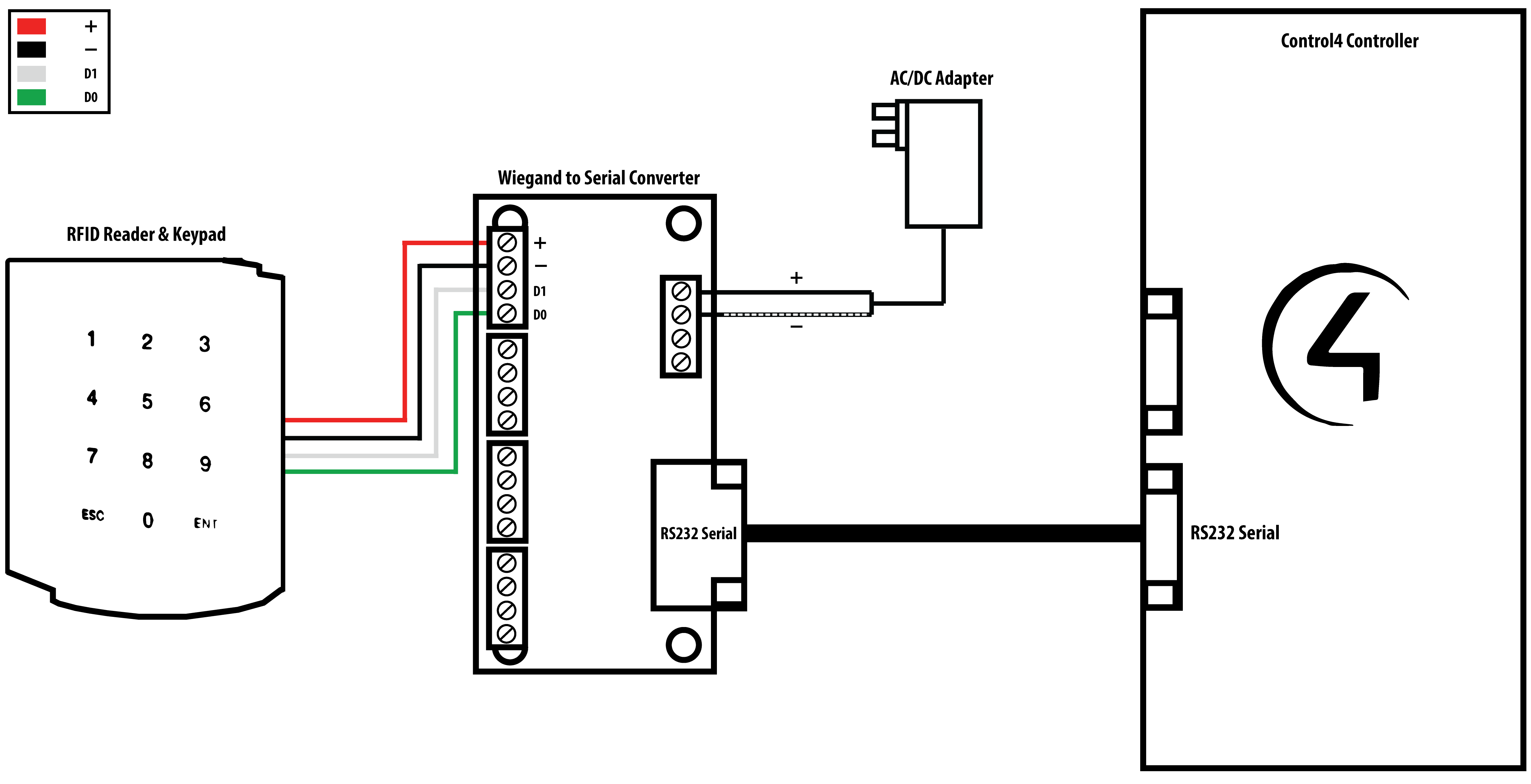
Wiegand card reader wiring diagram. It is possible to reuse existing Wiegand wiring for OSDP. Variety of access control card reader wiring diagram. It shows the components of the circuit as simplified shapes and also the power and signal connections between the tools.
Literally a circuit is the course that allows electrical energy to flow. GDS3710 wiegand input IF board connector Wiegandoutput Device Card reader GND WG_D1_OUT WG_D0_OUT LED WG_D1_IN WG_D0_IN BEEP 5VOptional 12V GND VCC GND LED D1 output D0 output BEEPER Power for GDS Wiegand 12V GND J4 J2 Note. 2 Wiegand reader input ports transient protected 8 Wiegand reader output ports transient protected opto-isolated 4 Wiegand outputs on the 4-port version Works with card formats up to 64 bits w no leading or trailing characters LED indicators show swipe activity on all ports.
Wiegand Card Reader Wiring Diagram It is far more helpful as a reference guide if anyone wants to know about the homes electrical system. Find the specific wiring configuration for your Wiegand reader or keypad in the documents that came with the reader. Wiegand reader wiring diagram A Beginner s Overview to Circuit Diagrams.
The Operation of LED is controlled by the Access Controller the LED operation may vary depending on the Access Controller software. Connect the Reader and Host together according to the wiring diagram below and the Host installation guide. Card reader actuator auto operator.
MiniProx Readers - Wiegand 5365B and Clock and Data 5368B. The legend for wiring is color coded according to the Wiegand Standard for the recommended cable but marking the wires will make future maintenance easier. The wiring in Wiegand devices makes the systems harder to duplicate.
With CAT5 cabling use 2 wires for GND and 2 wires for PWR. Wiegand wiring diagram Table 1. Indicating a read of the card.
If the Reader LED is controlled by the Host refer to the Host description of the LED. Reader Wire Color Controller Terminal Description Red VH 12V DC power to reader Black Gnd ground Green W0 Data 0 data. Common wiring diagrams.
Assortment of wiegand reader wiring diagram. A wiring diagram is a simplified traditional pictorial depiction of an electric circuit. The normal behavior the LED on card reader will turn Green to indicate that card is read and privileged.
244 If upgrading a Wiegand reader to OSDP do you need to also change the wiring as well. Below are the wiring diagram to connect the card reader using Wiegand Protocol. The following wiring diagram shows how to connect the reader to the controller in Wiegand mode.
Its components are shown by the pictorial to be easily identifiable. ProxPro WiegandClock-and-Data Installation Guide 5355A-900 Rev. A wiring diagram is a streamlined traditional photographic representation of an electric circuit.
Double door alk wiring. Auto operator amd latch retraction wiring. The function is the very same.
They are often photos attached with highly-detailed drawings or labels of the. JOHNSON CONTROLS EP1501 PoE Support for AD-300 Locks. However a bank card will use a band of ferromagnetic material instead of wiring.
After wiring the Reader and power supply the Reader is ready to be tested. In summary Wiegand devices are cards and any kind of data reader that operates on a special wire communication system. These need to be used with a Wiegand sensor in order to work.
However using simple stranded cable typical of Wiegand access control readers does not typically meet the TIA485EIA-RS485 specification for twisted pair recommendations. An initial look at a circuit layout may be complicated yet if you can review a train map you could review schematics. Wiegand wiring diagram Callout Description A Mullion reader B Single Gang read.
It shows the components of the circuit as streamlined forms as well as the power and signal connections in between the gadgets. The Wiegand interface uses three wires one common ground GND and two data transmissions D0 and D1. Input power 9-12VDC at 100 mA.
The following common wiring diagrams are available. Is the least efficient diagram among the electrical wiring diagram. Below is the standard wiring for most HID proximity card readers and keypads.
2-3 with Wiegand AD-400. Getting from factor A to aim B. Wiring Diagram INSTALLATION MANUAL NANOPW - NANOPB Wiegand 125 Khz Proximity Reader 5 WIRING DIAGRAM When powered Cable - Green LED illuminates for 1 second - Red LED illuminates for 1 second Input voltage 12V dc - Buzzer sounds for 1 second.
Present an ID card to the Reader and the LED should momentarily turn green indicating a read of the card. Please make sure connect the GND of wieganddevice and GDS wiegandport. Wiegand wiring diagram using CAT5 cable Note.
If the Reader LED is controlled by the Host refer to the. Its components are shown by the pictorial to be easily identifiable. Is the least efficient diagram among the electrical wiring diagram.
The terminals is also shown on the back label as well as in the diagram below. The descriptions are on the PCB guard in the reader. Wiegand Wiring Diagram It is far more helpful as a reference guide if anyone wants to know about the homes electrical system.
 Dm 20 Wiring Examples Knowledge Center
 Barcode Scanner Connected To Arduino Arduino Barcode Barcode Scanner
 Xpressfreedom Ethernet To Wiegand Converter Telaeris Inc Access Control Control Interactive
 Stm32 Nucleo F401re Pinout Microcontrollers 10 Things 9 And 10


