Limit Switch Wiring Diagram Terminal 5
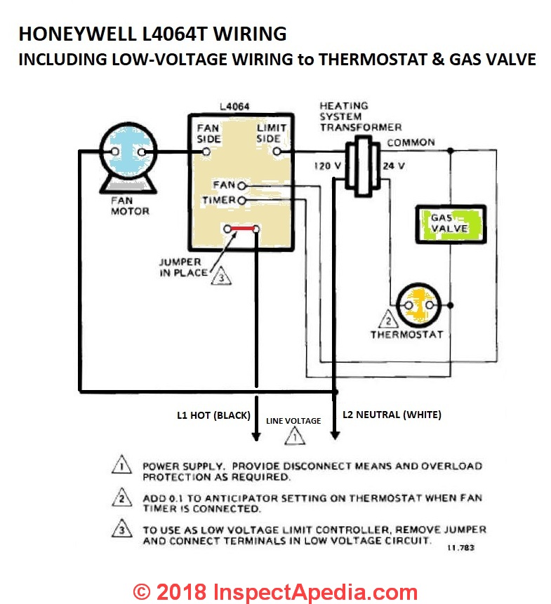
The following instructions go over the hardware and software settings required to set up Homing including auto-squaring of your gantry for dual-drive machines and Limits with our inductive proximity switches. Make L1 HOT on 120V installation Limit Switch Fan Switch Fan Motor Optional Remote Manual Switch For Summer Fan To Low Voltage Or Millivolt Burner Circuit L1.
 Intermediate Switch 3 Way Switch Connection Wiring Diagram Youtube
On terminal strip Ambient temperature range -20 C to 80 C APL 4 Series Limit Switch CSA Approved Class I.

Limit switch wiring diagram terminal 5. To reverse direction of rotation of the RW motor Swap connections V1 and W1 on the electrical motor connection strip. July 5 2019 4 Wire Harness July 5 2019 1994 Ford F150 Tail Light Wiring Diagram July 5 2019 3 Way Switch Common Terminal July 4 2019 Digital Thermostat Circuit July 4 2019 Split Circuit Outlet July 4 2019 Low Voltage. Soldering Limit Switches If you purchased a limit switch kit with your X-Carve.
Four threaded holes in the back plate are used to fasten the mounting adapter. Wiring a Switch to a Wall Outlet Here a receptacle outlet is controlled with a single-pole switch. End Stop Z Terminal - NC Terminal Z Axis Limit Switch COM Terminal - End Stop GND Terminal Cheers mate.
The power input terminal is called the common terminal and is used to connect the switch to a power source. For instance a limit switch for the X- limit will be connected from the ELX- terminal to the NO connection of the limit switch then a connection from the GND terminal on the laser controller to the COM connection to the same limit. Diagram Using Limit In Line Voltage Circuit L1 Line L2 Note.
On the opposite side the housing is prepared for mounting an additional cable connector for passing on the control signal for a solenoid valve è terminal diagram in Fig5. 00 Get it as soon as Mon Feb 22. On the side the limit switch attachment has a cable connector for the wiring è Fig1 aJ.
In this diagram 2-wire cable runs between SW1 and the. A limit switch is used to control electrical devices by breaking and completing electrical circuits. It has three terminals.
Maxairtechcom 3 TECHNOPOLYMER LIMIT SWITCH OPTIONS Switch 1 Up-Open Switch 2 Under-Closed Solenoid Valve Pass Thru WIRING DIAGRAM SPDT MECHANICAL SWITCHES with 8-Point Terminal Strip on a printed. Wiring diagram 1-phase 5-wire motor gearbox RSU limit switch Notes. Please refer to the wiring diagram enclosed for terminal numbering.
This is commonly used to turn a table lamp on and off when entering a room. A wiring diagram is a streamlined conventional photographic depiction of an electric circuit. APL 3 Series Limit Switch CSA Approved Type 4X Rugged and flexible design Dual 12 NPT conduit entries 8 pts.
This diagram should help clarify this step and will be referenced again when you wire your stepper cable to the gShield in the Electronics section. Both heating resistor 7 and torque limit switches 5 must be integrated into your control system in order to prevent potential damage to the actuator or valve. Thats the way I assumed it should work but I was not sure if it could work with NC switches as the wiki says its NO switches.
You can also look for some pictures that related to Wiring Diagram by scroll down to collection on below this picture. HMY 31973K4183 SPB501 551508G Waterproof Ignition Key Starter Switch with 3 Position 5 Terminal 2 Keys Replaced with Cars Motorcycles Boats TractorTrailerDiggerAgricultura 1100 11. If a switching output is strictly PNP or NPN the external connection through the loadThanks for purchasing our inductive Proximity Limit Switch Kit.
Wiring Diagram Book A1 15 B1 B2 16 18 B3 A2 B1 B3 15 Supply voltage 16 18 L M H 2 Levels B2 L1 F U 1 460 V F U 2 L2 L3 GND H1 H3 H2 H4 F U 3 X1A F U 4 F U 5 X2A R. Variety of honeywell limit switch wiring diagram. To reverse the limit switches of the.
It reveals the components of the circuit as streamlined shapes and the power.
 6 Terminal Toggle Diagram In 2021 Toggle Switch Electronic Schematics Portable Solar Generator
 How To Wire Up A Micro Switch Youtube
 Circuit Diagrams Of Safety Components Technical Guide Australia Omron Ia
 Fan Limit Control Installation Faqs
 Limit Switch Explained Working Principles Realpars
